Quote:
Originally Posted by xxxJohnBoyxxx  DIY Secondary Air Pump Simulator. Secondary Air Pump Parts Needed (All Purchased @ Radio Shack): 1 - Component PC board (#276-149 $1.99) 1 - Component Project Enclosure (#270-1802 $2.69) 1 - SPDT * PC relay miniature 12vdc 10V (#275-248 $4.69) 1 5V Voltage regulator (# 276-1770 $1.59) 1 - 100K ohm Micro Potentiometer (#271-284 $1.49) Tools Needed: Soldering pen 7 watts or higher Solder Wire Digital volt meter Place relay, potentiometer and regulator on board as shown in picture. Solder all pins on back side of board. Go to wiring diagram and make connections. When finished test unit by hooking to 12 volts and set potentiometer with a screwdriver to 200mv from pin DME wire to ground. Potentiometer should be between 45,000 and 50,000 ohms if you want to ohm it out. Questions to jsmith50@tampabay.rr.com ***This is for off road use only*** ***I accept no responsibility for items burned out or damaged by mis-use of this devise. The DME & O2 are sensitive devises and can be destroyed by sending the wrong voltage to the units*** Top Of Board 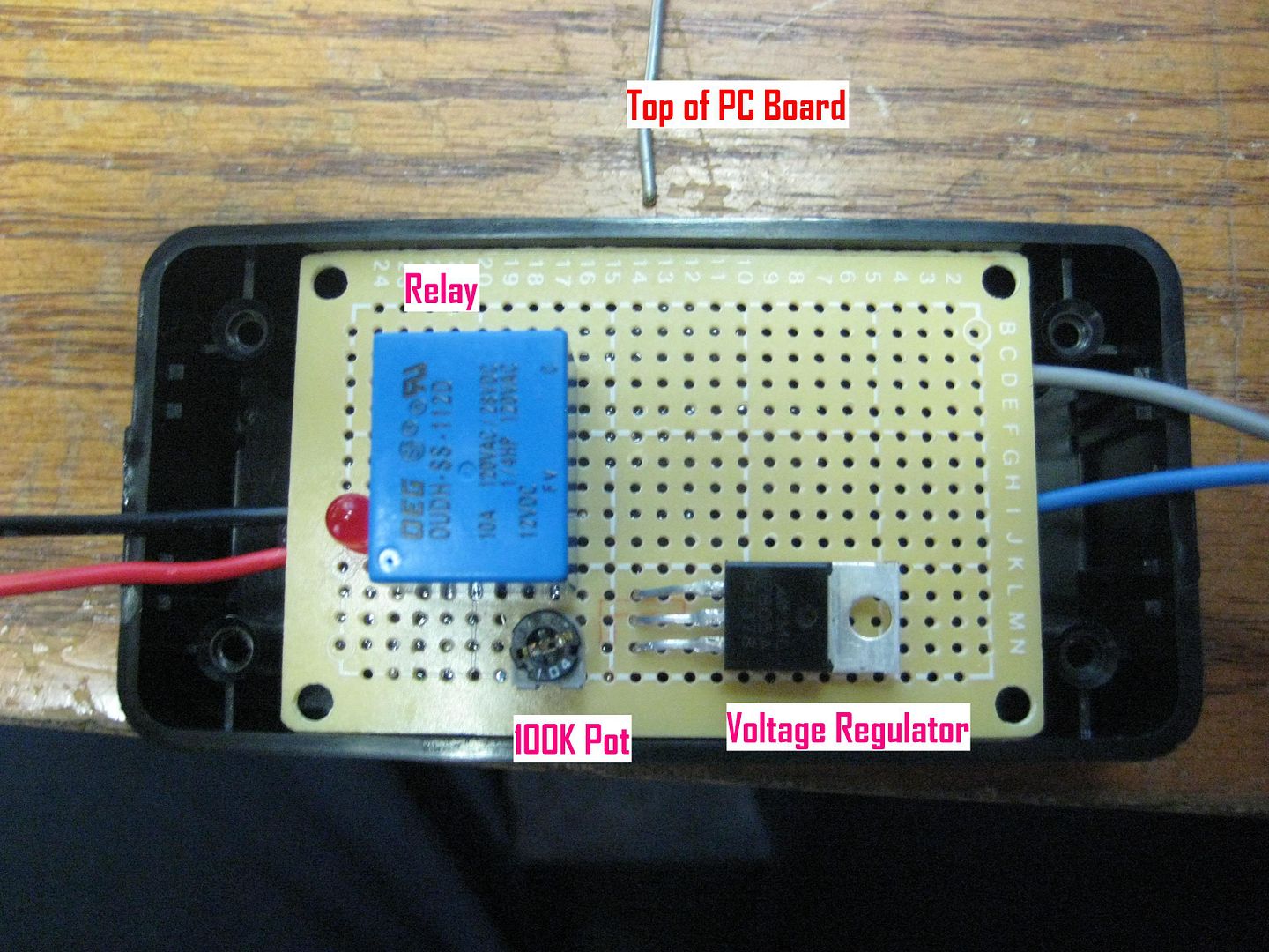 Bottom of Board Bottom of Board 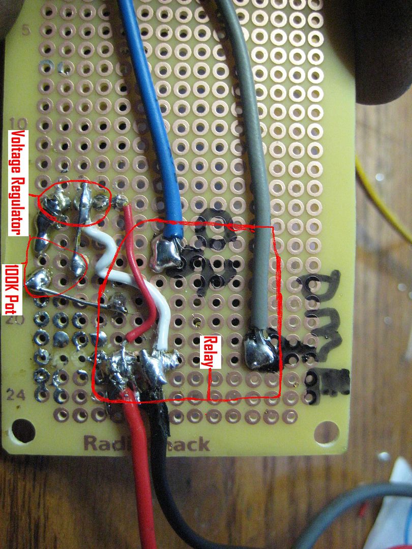 Wiring Wiring 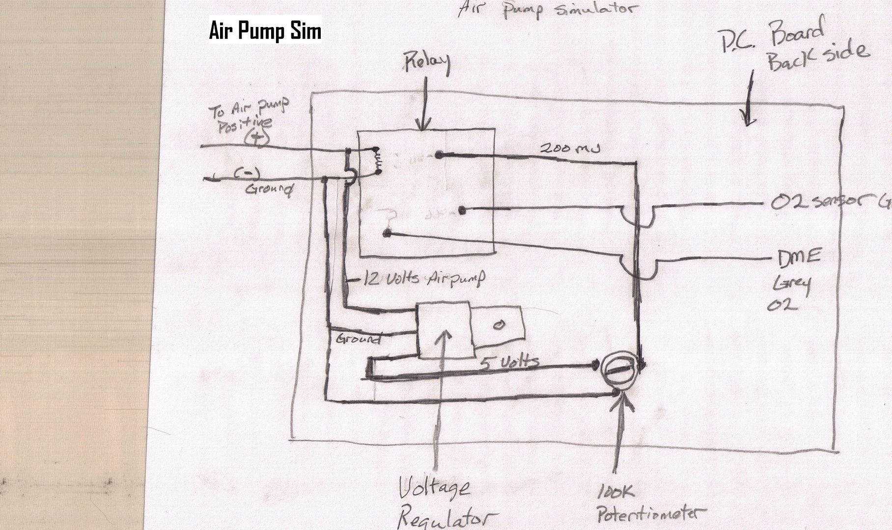 |
Where do I locate the DME and O2 sensor from the car to connect the Grey DME wire and Blue O2 sensor wire?
Do you have pictures to show how the wires are connected from the built simulator to the car DME and O2 unit?